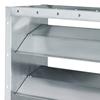
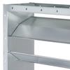
Parallel blades

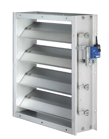
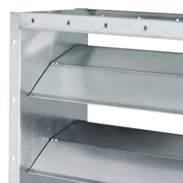
Parallel blades
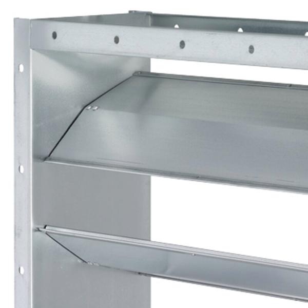
Opposed blades
Special characteristics
Construction
Duct connection
Only for multileaf dampers made of galvanised sheet steel with brass or stainless steel bearing bushes (JZ-...-M, JZ-...-E)
Accessories
Standards and guidelines
① Casing
② Opposed blades
③ External linkage
④ Actuator
⑤ Transverse link
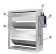
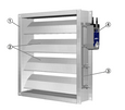
Multileaf dampers with external linkage can have parallel action blades or opposed action blades. An external linkage transfers the synchronous rotational movement from the drive arm to the individual blades. Even very large multileaf dampers can be safely opened and closed with this type of linkage. Opposed action blades close at various speeds as the linkage includes a transverse link. This facilitates the closing process and reduces the air leakage in closed multileaf dampers.
The torques for operating multileaf dampers must be dimensioned in such a way that the damper can be safely opened and closed. For closure, the torque must suffice to ensure complete shut-off by the blades. Opening is initiated without the impact of aerodynamic forces. When air flows through the damper, the aerodynamic forces of the airflow create a closing force (torque) on the blades; this happens independently of the direction of the airflow. This closing force must be countered, or overcome. The blade angle α with the largest torque depends, among other things, on the fan characteristics.
Nominal sizes | 200 × 180 – 2000 × 1995 mm |
Operating temperature | -20 °C to 100 °C |
H | B | |||||||||
200 | 400 | 600 | 800 | 1000 | 1200 | 1400 | 1600 | 1800 | 2000 | |
180 – 1995 | 10 | 10 | 10 | 10 | 10 | 10 | 10 | 10 | 10 | 10 |
H | B | |||||||||
200 | 400 | 600 | 800 | 1000 | 1200 | 1400 | 1600 | 1800 | 2000 | |
180 | 0.03 | 0.06 | 0.09 | 0.12 | 0.15 | 0.18 | 0.21 | 0.24 | 0.27 | 0.3 |
345 | 0.06 | 0.11 | 0.17 | 0.23 | 0.28 | 0.34 | 0.4 | 0.45 | 0.51 | 0.57 |
510 | 0.08 | 0.17 | 0.25 | 0.33 | 0.42 | 0.5 | 0.58 | 0.67 | 0.75 | 0.83 |
675 | 0.11 | 0.22 | 0.33 | 0.44 | 0.55 | 0.66 | 0.77 | 0.88 | 0.99 | 1.1 |
840 | 0.14 | 0.27 | 0.41 | 0.55 | 0.69 | 0.82 | 0.96 | 1.1 | 1.23 | 1.37 |
1005 | 0.16 | 0.33 | 0.49 | 0.66 | 0.82 | 0.98 | 1.15 | 1.31 | 1.47 | 1.64 |
1170 | 0.19 | 0.38 | 0.57 | 0.76 | 0.95 | 1.14 | 1.33 | 1.52 | 1.72 | 1.91 |
1335 | 0.22 | 0.43 | 0.65 | 0.87 | 1.09 | 1.3 | 1.52 | 1.74 | 1.96 | 2.17 |
1500 | 0.24 | 0.49 | 0.73 | 0.98 | 1.22 | 1.47 | 1.71 | 1.95 | 2.2 | 2.44 |
1665 | 0.27 | 0.54 | 0.81 | 1.08 | 1.36 | 1.63 | 1.9 | 2.17 | 2.44 | 2.71 |
1830 | 0.3 | 0.6 | 0.89 | 1.19 | 1.49 | 1.79 | 2.08 | 2.38 | 2.68 | 2.98 |
1995 | 0.32 | 0.65 | 0.97 | 1.3 | 1.62 | 1.95 | 2.27 | 2.6 | 2.92 | 3.25 |
Construction | B | ||||||
800 | 1000 | 1200 | 1400 | 1600 | 1800 | 2000 | |
Standard construction | 2500 | 2000 | 1650 | 1400 | 1250 | 1100 | 1000 |
Brass bearings (-M) | 3000 | 2500 | 2200 | 1950 | 1750 | 1600 | 1500 |
Stainless steel bearings (-E) | 3000 | 2500 | 2200 | 1950 | 1750 | 1600 | 1500 |
Reinforced blades (-M-V, -E-V) | 3500 | 3000 | 2700 | 2500 | 2300 | 2100 | 2000 |
Δpt [Pa] | Area B × H [m²] | |||||||
0.14 | 0.2 | 0.4 | 0.6 | 0.8 | 1.2 | 2 | 4 | |
100 | 57 | 58 | 61 | 63 | 64 | 66 | 68 | 71 |
200 | 63 | 65 | 68 | 69 | 71 | 72 | 75 | 77 |
500 | 71 | 72 | 76 | 78 | 79 | 81 | 83 | 84 |
1000 | 78 | 80 | 82 | 84 | 85 | 88 | 90 | >90 |
1500 | 81 | 83 | 86 | 88 | 89 | >90 | >90 | >90 |
2000 | 84 | 85 | 89 | >90 | >90 | >90 | >90 | >90 |
Δpt [Pa] | Area B × H [m²] | |||||||
0.14 | 0.2 | 0.4 | 0.6 | 0.8 | 1.2 | 2 | 4 | |
100 | 57 | 58 | 61 | 63 | 64 | 64 | 68 | 71 |
200 | 63 | 65 | 68 | 69 | 71 | 71 | 75 | 78 |
500 | 71 | 72 | 76 | 78 | 79 | 79 | 85 | 87 |
1000 | 78 | 80 | 82 | 84 | 85 | 85 | 89 | >90 |
Δpt [Pa] | Area B × H [m²] | |||||||
0.14 | 0.2 | 0.4 | 0.6 | 0.8 | 1.2 | 2 | 4 | |
1500 | 81 | 82 | 86 | 88 | 89 | 89 | >90 | >90 |
2000 | 84 | 86 | 89 | >90 | 90 | >90 | >90 | >90 |
Rectangular multileaf dampers for volume flow and pressure control as well as for shutting off ducts and openings in walls and ceiling slabs. Ready-to-operate unit which consists of the casing, aerofoil blades and the blade mechanism. Flanges on both sides, suitable for duct connection. The blade position is indicated externally by a notch in the blade shaft extension. Casing air leakage to EN 1751, class C.
Special characteristics
Material and surfaces
Construction
Technical data
Sizing data
Life cycle assessment
| JZ | – | P | – | A2 | – | G | – | M | – | – | L | / | 1000 × 1005 | / | ER | / | Z64 | / | NC | / | P1 - RAL 9010 | |
| | | | | | | | | | | | | | | | | | | | | | | | | |||||||||||
| 1 | 2 | 3 | 4 | 5 | 6 | 7 | 8 | 9 | 10 | 11 | 12 |
1 Type
JZ Multileaf damper
2 Function
S Opposed (standard)
P Parallel
3 Material
No entry: galvanised steel
A2 Stainless steel
4 Duct connection
No entry: corner holes on both sides,
G Flange holes on both sides (no corner holes)
5 Bearings
No entry: plastic bearings
M Brass bearings
E Stainless steel bearings
6 Construction of blades
Only for galvanised multileaf dampers with brass or stainless steel bearing bushes
V Reinforced blades, available from width 800 mm
7 Operating side
No entry: right
L left
8 Nominal size [mm]
Specify size width × height
Galvanised steel variants are available with the width or height subdivided
Width > 2000: width subdivided
Height > 1995: height subdivided
9 Installation subframe
No entry: without installation subframe
ER With installation subframe (duct connection G only)
10 Attachments
No entry: without attachments
Z04 – Z07 Hold open device
Z12 – Z51 Actuators
ZF01 – ZF15 Spring return actuators
Z60 – Z77 Pneumatic actuators
Explosion-proof actuator
Z1EX, Z3EX Electrical
Z60EX – Z77EX Pneumatic
11 Damper blade safety function
Only with spring return actuators or pneumatic actuators
NO pressure off/power off to OPEN (Normally Open)
NC pressure off/power off to CLOSE (Normally Closed)
12 Surface
No entry: standard construction
P1 powder-coated, specify RAL CLASSIC colour
Gloss level
RAL 9010 GU 50
RAL 9006 GU 30
All other RAL colours GU 70
Order example: JZ–S–G–M–V–L/800×510/ER/Z43
| Function | Opposed |
| Material | Galvanised steel |
| Duct connection | Flange holes on both sides |
| Bearings | Brass bearings |
| Construction of blades | Reinforced blades |
| Operating side | Left |
| Nominal size | 800 × 510 mm |
| Installation subframe | With |
| Attachments | Actuator, 10 Nm, 230 V AC, 3-point |
| User interface | Standard construction |
Kontakt
Tu smo za vas
Preporučite ovu stranicu slanjem poveznice poštom.
Podijeli stranicu
Zahvaljujemo na preporuci!
Vaša je preporuka poslana i trebala bi stići uskoro.
Kontakt
Tu smo za vas

Navedite svoju poruku i vrstu zahtjeva
Tel.: +385 1 61 55 401 | +385 1 61 58 598
Kontakt
Zahvaljujemo na vašoj poruci!
Vaša je poruka poslana i ubrzo će biti obrađena.
Naš odjel za servisne zahtjeve što skorije će vas kontaktirati.
Za opća pitanja u vezi s proizvodima ili uslugama možete i nazvati:
Tel.: +385 1 61 55 401 | Faks: +385 1 61 58 598
Kontakt
Tu smo za vas
Navedite svoju poruku i vrstu zahtjeva
Tel.: +385 1 61 55 401 | +385 1 61 58 598
Kontakt
Zahvaljujemo na vašoj poruci!
Vaša je poruka poslana i ubrzo će biti obrađena.
Naš odjel za servisne zahtjeve što skorije će vas kontaktirati.
Za opća pitanja u vezi s proizvodima ili uslugama možete i nazvati:
Tel.: +385 1 61 55 401 | Faks: +385 1 61 58 598